Introduction to Software Defined Radio
Radio signals are borderline black magic to me. The fact that energy can be propagated through thin air by just wiggling some electrons in a periodic wave blows my mind. Furthermore, the energy generated from the wiggling electron can be picked up by other electrons such that information can be propagated wirelessly across vast distances. This simple principle enables our modern world of telecommunications from RADAR, interstellar space travel, live television, satellites, to WiFi, cellular, and bluetooth. I’ve always wanted to explore the world of RF technologies so when I got myself an RTL-SDR this door finally opened.
Software-Defined Radio
A software-defined radio, or SDR, is a piece of equipment that reads raw radio signal data from an antenna and uses a computer to filter the signal into a usable format. This is distinct from how typical radios work because “normal” radios have built-in electrical components (in the form of capacitors, resistors, inductors, etc…) that perform the filtering automatically. SDRs are thus interesting because the computer is reprogrammable which allows custom modifications to how the SDR works. In other words, a single SDR can be programmed to listen on FM radio station like in a car, NOAA weather stations, reading satellite images, tracking nearby airplanes, listening to amateur radio operators, and even lock GPS position signals! These exciting applications for SDRs fueled my enthusiasm to “surf the spectrum” and discover whats going on in the airwaves around me.
RTL-SDR
Generally speaking, SDRs are very expensive pieces of hardware. The ones used in laboratories typically cost in the thousands of dollars 1 so when people noticed some consumer USB TV tuners could be hacked to spit out raw RF data a whole cottage industry of hobbyist SDR users emerged. RTL-SDR is such an example that uses a R820T tuner coupled with a RTL2832U chip to serve raw RF data to a computer: (diagram from the R820T datasheet)
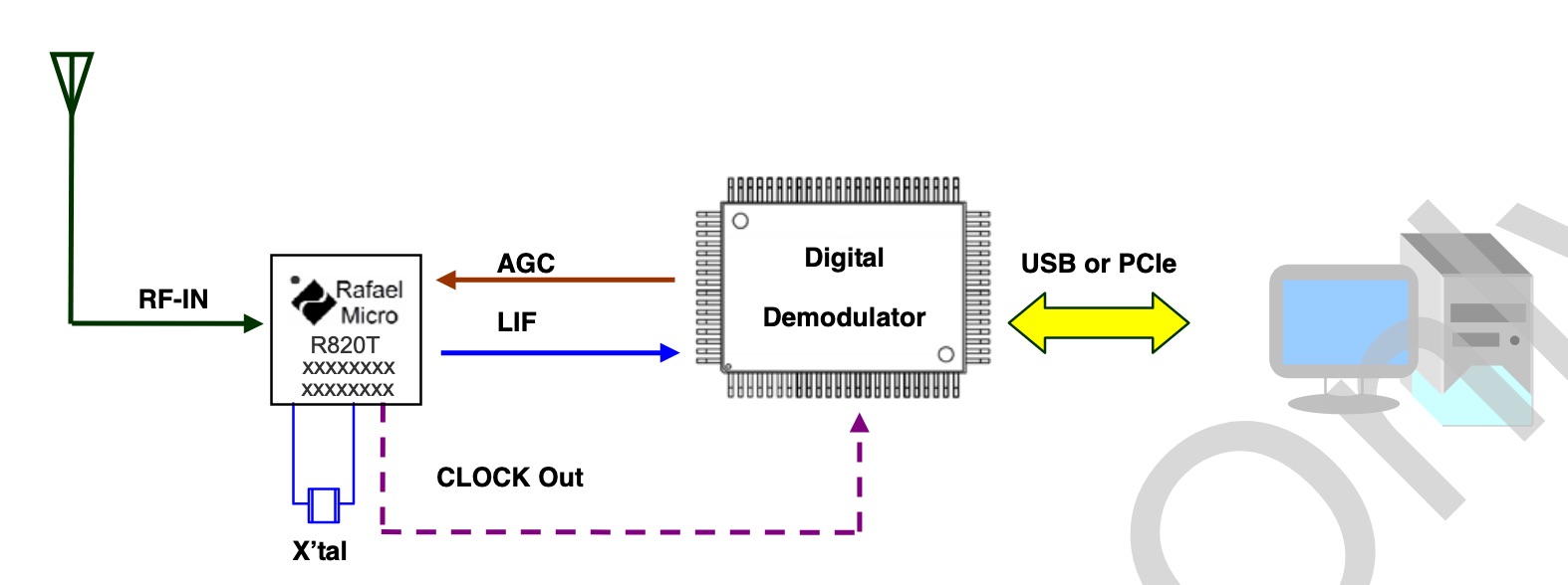
I’m still learning the basics of how modern radios work, but my current understanding is the R820T tuner contains analog circuitry to convert antenna signals into an intermediate frequency. My guess is that the R820T is a superheterodyne receiver embedded in a chip. The output intermediate frequency signal is then transferred to the RTL2832 demodulator chip for digitization, where its onboard analog-to-digital (ADC) converter generates a stream of bytes for the computer to pick up. The RTL2832 is normally used for demodulating–a process to separate the signal from carrier–TV signals but in this case the RTL-SDR driver skips that step and goes for the raw IQ data instead. The computer then runs a program to demodulate those IQ samples into audio (like FM or AM) or decode it into a stream of bytes for digital information like ADS-B or GPS.
In-Phase & Quadrature Signals
To be honest I’m not a signal-processing expert so I’m not exactly sure what this “complex-valued” signal really means. It’s supposed to be a better way analyze RF signals compared to single-dimension data, but so far I’m still in the process of figuring out what that means. I’m looking through some references as an ongoing effort to understand:
- Quadrature Signals Explained
- In-phase and Quadrature
- DSPRelated Article
- Understanding IQ Signals and Quadrature Modulation
CubicSDR
What the SDR sends to the computer is a stream of bytes representing the IQ signal sampled from the ADC. Next, the computer must apply signal processing algorithms to filter IQ samples into a data–this is where the “software” part of SDR comes in. CubicSDR is an example of such a software that can read IQ data and demodulate them into a variety of formats2.
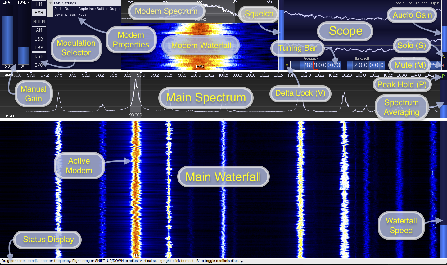
The interface is fairly straightforward; just select a demodulator then click on the spectrum waterfall to begin listening in on a frequency band. I had a great deal of fun just surfing the airwaves looking for random signals to look at. There is a surprising amount of traffic going on at any given time and I was rather shocked when I discovered signals frequently overlapped with each other. It was interesting too to see what digital and analog signals looked like on a spectrum. Turns out there are a lot of interesting visual patterns that can help identify what a mystery signal might contain. In fact, there is a signal identification wiki that curates a collection of imagery to help users figure out what they’re looking at. Here’s what FM radio looks like for example; its this fuzzy band that resembles an audio waveform with an occasional HD-radio signal on the sides. The screenshot below is tuned into the N6NFI repeater in Palo Alto, California:
Surfing the spectrum was a lot of fun. I usually start by listening in on a local FM radio station since their signals are usually very strong. Then I start looking around for random signals that pop in and out of the spectrum. Sometimes I come across law-enforcement and emergency services, other times I encounter air-traffic-control conversations. But most signals were not super interesting unfortunately. Digital signals have cool patterns on the spectrum but are unintelligible because I don’t have the decoder to tell me what’s in there. Most of the interesting stuff is people’s conversations on AM and narrow-band FM such as ATC and amateur radio respectively. I like to browse databases like RadioReference and LiveATC that shows who is talking on what frequencies.
Tracking Airplanes
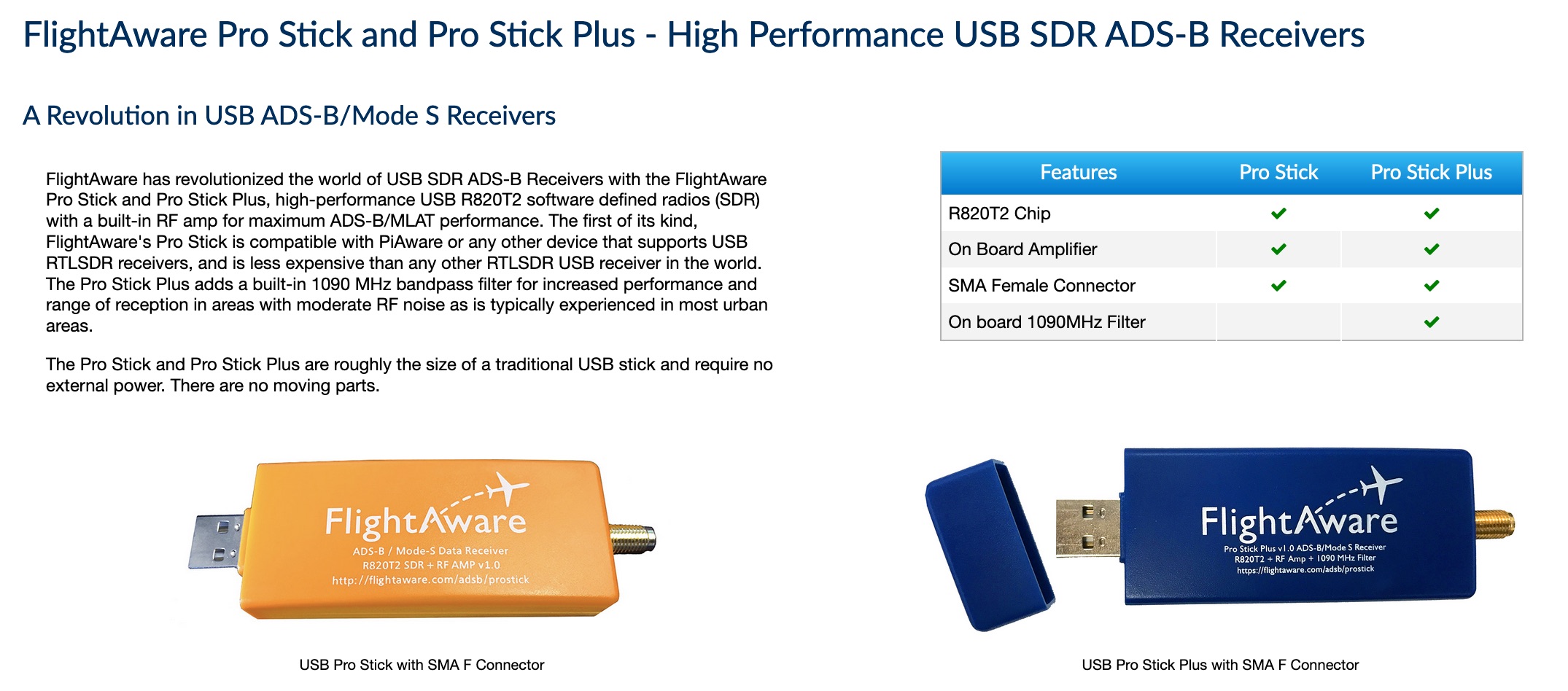
One of the coolest applications of SDRs is tracking airplanes using a protocol called automatic-dependent-surveillance broadcast, or ADSB. ADSB is a way for airplanes to share their identification and positional information with interested parties, usually air traffic controllers and other airplanes nearby. Aircraft affixed with ADSB transponders periodically transmit a short digital radio message that contains identification and position information reported by the aircraft’s onboard GPS. These messages are not encrypted and can be read by any RF receiver on the right frequency with the right decoder. Hence as more and more airplanes installed ADSB transponders a whole cottage industry of real-time aircraft tracking emerged as global networks of ADSB receivers continuously feed huge databases of live flight data on websites like FlightRadar and Flightaware. In fact, users can contribute to these databases by purchasing specialized SDR USB dongles that track local flights in the surrounding areas. Flightaware sells these USB sticks as a turnkey solution:
ADS-B
The full protocol format for ADSB is quite detailed but thankfully Junzi Sun has documented them on his website The 1090 Megahertz Riddle. There’s also a great website on Stanford’s EE179 course page talking about basic ADSB decoding using Matlab which served as a good starting point for my implementation.
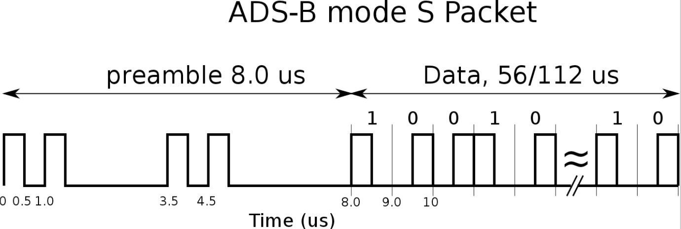
Long story short, ADSB is amplitude-modulated on a 1090 megahertz carrier that encodes a series of split-phase pulses 56 or 112 bits long at a 2 megahertz sample rate. These frames contain a special “starting signal” called a preamble that indicates the start of a transmission:
Decoders then convert the split-phase pulses into a bytestream that contains encoded data about the identity of the transmitting aircraft and associated payload data. Junzi’s page on ADSB basics talk about how a message is structured in various different formats for different types of payloads. For example, there are different schemas for aircraft identification (callsign-type messages) versus positional latitude-longitude messages; thus the decoding program must use multiple messages to accumulate its knowledge about a particular flight.
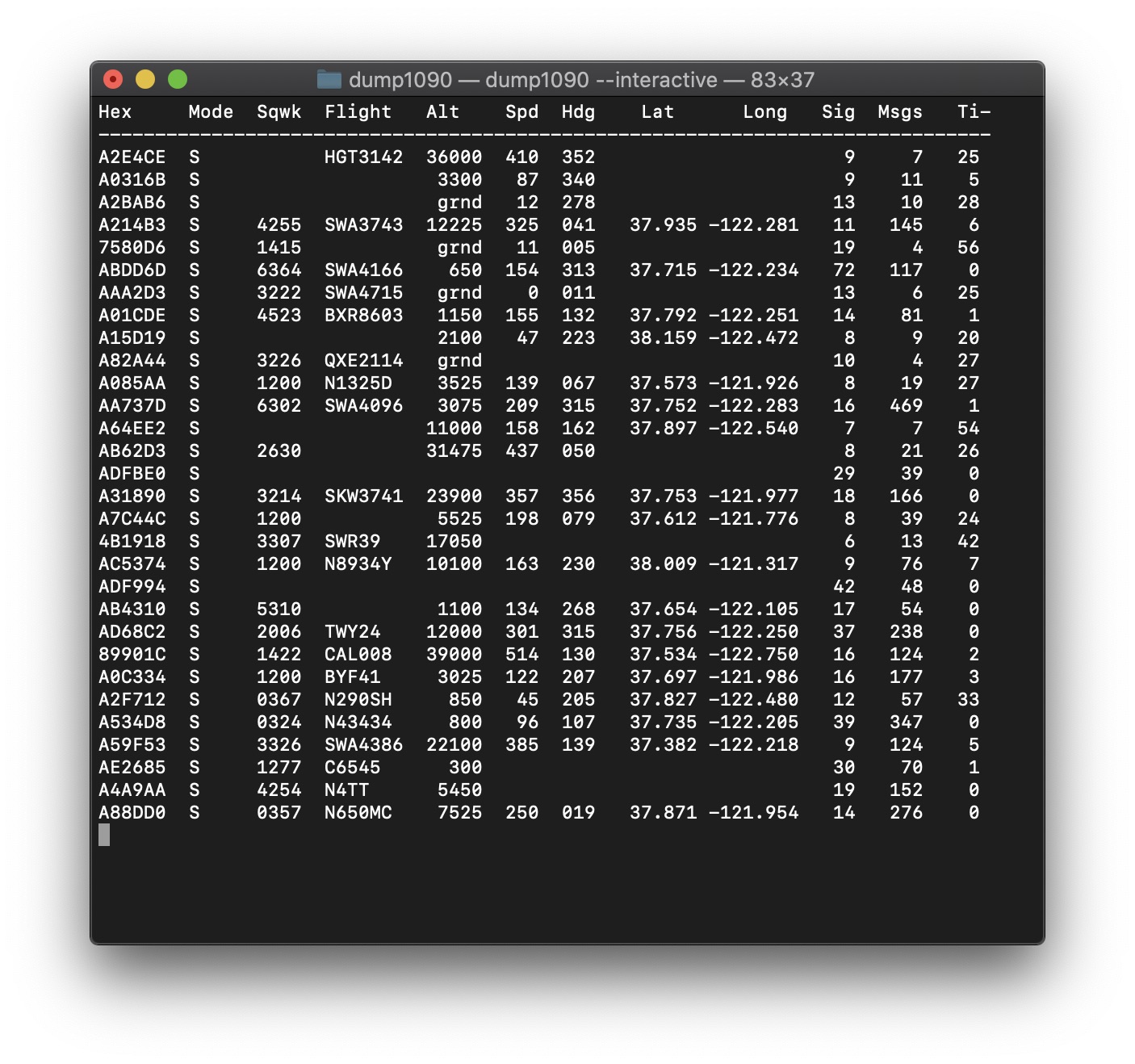
Dump1090 is a great program for getting a head start on ADSB decoding. It has several error-correction and signal tweaking features that make it a very robust decoder for the average enthusiast. The source code also helped me get started on my own decoder for CubicSDR.
Error Correction
A critical aspect of digital signals communications concerns data integrity. Many communication mediums are noisy and can corrupt the signals in transmission; wireless radio is probably notorious in these aspects. Hence many protocols include a way of checking if the message came across intact through the application of error-detecting codes, or checksums. ADSB uses a particular type of cyclic-redundancy-check (CRC) checksum that generates a 24-bit remainder value appended to the end of the message. The decoder computes the CRC of every message frame and compares the its calculated remainder against the last 24 bits of the frame. If they match, then the message is intact. Otherwise the message was corrupted in transit, and the message should be ignored. This diagram from Junzi’s page gives an overview of the process:

CRCs are based on this idea of polynomial division across the finite field GF(2). It took a while to wrap my head around this kind of math so I found Ben Eater’s walkthrough very helpful in understanding how all the pieces fit together:
If I had to summarize, CRC uses a special generator polynomial that possesses error-detecting properties as a divisor. The message (encoded as a polynomial) itself is the dividend that is divided by the divisor i.e. the generator. The resulting quotient is not used, rather the remainder of this division operation serves as the checksum. There’s a twist though, this is not simply dividing two polynomials! As it turns out, the coefficients of the polynomials must be either 1 or 0 such that the remainder polynomial can be encoded back as binary. Enter finite fields: If the coefficients of the polynomials are instead values of the finite field GF(2) (which contains only 1 or 0), then the division operation will always yield a binary-encodable polynomial remainder. Furthermore, the cherry on top is the fact that division operations under GF(2) polynomials exactly match the truth table of the exclusive-or (XOR) operator. XOR is a common elementary operation on computers so CRC algorithms are widely used in digital communication systems for fast and accurate error detection. If you’re more hardcore, CRC can also correct for errors in the bitstream. Advanced decoders can use the CRC remainders to figure out which bits in the frame were corrupted and correct them on the fly!
This is so incredibly cool! My decoder relies on the CRC to determine if it has a valid message and without it, ADSB would be virtually useless since valid messages would be indistinguishable from random noise. Going through this exercise helped me develop an appreciation for error correction and signal processing and how much these technologies underpin the infrastructure we take for granted today.
ADSB in CubicSDR
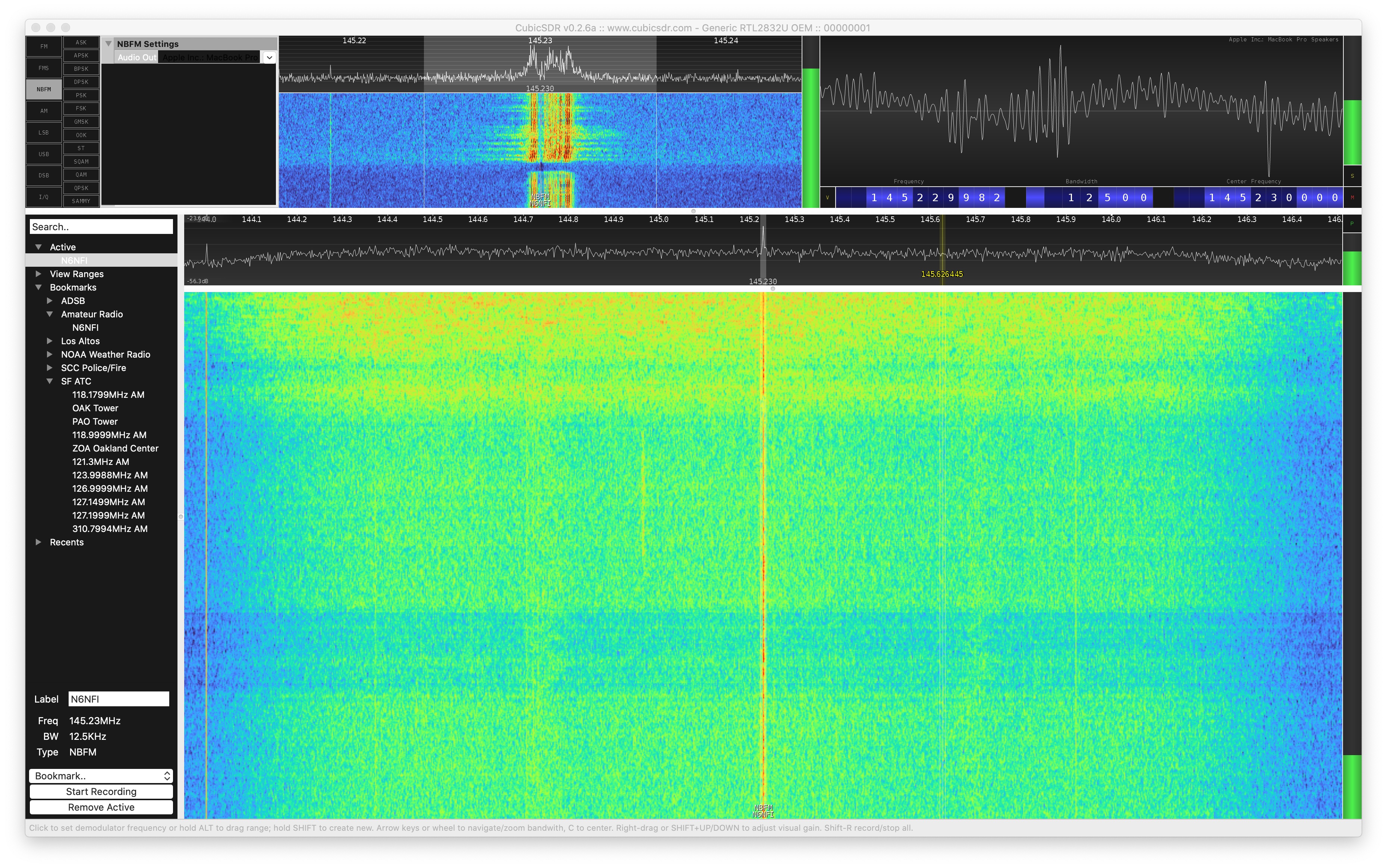
A lot of what I learned about ADSB came from integrating a decoder for the CubicSDR application. CubicSDR is open source so I started tinkering with it to add in a new decoder (I called it “SAMMY” for now) that will display a “virtual radar” of nearby aircraft. My ultimate goal was to make CubicSDR display a chart of tracked aircraft along with an interactive map that plots aircraft positions in real time.
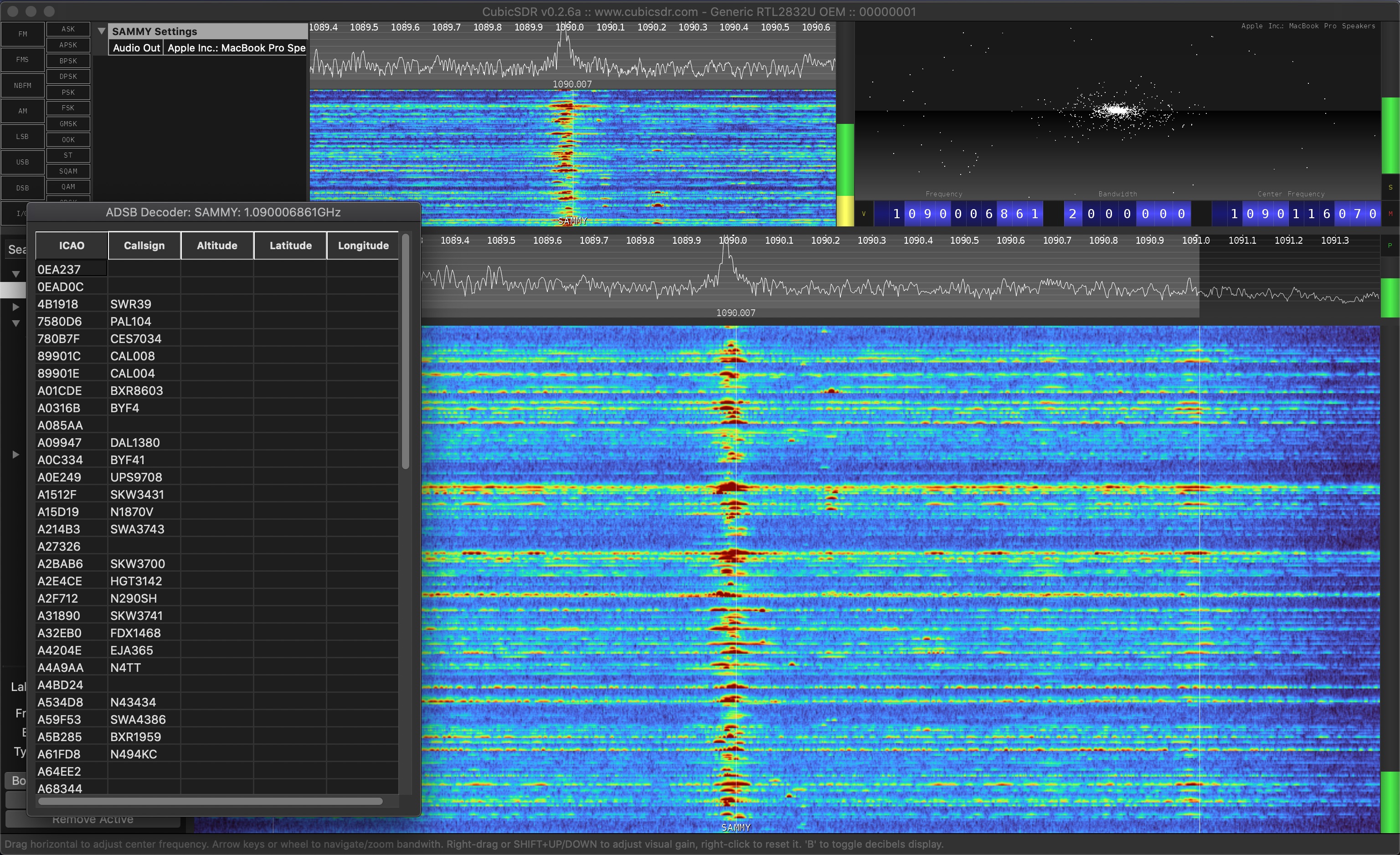
My current progress at the time of writing is shown in the screenshot above. I made several modifications to CubicSDR to increase its default bandwidth3 and added a new kind of digital console to display a table of tracked aircraft. Right now I have a version that shows the ICAO and callsigns of each aircraft in the table. And I think this is a good milestone as I continue implementing the rest of the decoder and map display. I’ve saved my changes to a Github repo here: masoug/CubicSDR
Next Steps
There’s still a lot of work to be done to achieve the virtual radar in CubicSDR milestone:
- My immediate next step is to implement the lat-long decoder portion of the ADSB protocol. It uses something called compact position reporting (CPR) to specify a precise lat-long location using just a few bits. This is a little tricky for me to understand and I’m currently looking through various sources to get a better idea of how exactly it works.
- Once I’ve crossed the milestone of getting lat-long positions the next thing to do is to plot the positions on the map. There’s a library called Mapnik that renders vector map files really nicely so I’ll have to block out some time maybe across a weekend to integrate it into CubicSDR.
- What would be really cool is if I could “smooth” out the aircraft trajectories using a Kalman Filter so aircraft motion in the virtual radar appear natural. The good news is that ADSB provides some level of positional uncertainty information in its lat-long messages which should feed into a Kalman Filter fairly naturally. I’m not exactly sure how this will turn out, but I hope it works and looks cool.
I hope to keep this an ongoing project in the background so there’ll probably be follow-up blog posts documenting my progress listed above.
Further Adventures
In the future I’m excited to checkout the world of GPS using SDR. It’s definitely possible as illustrated by this Tech Minds video but I’d like to try my hand at writing a decoder and solver myself. GPS is far more challenging to decode and use than ADSB, so I’m frankly not expecting to get on this anytime too soon. But it’s a huge payoff if I can get it to actually work because GPS is truly awesome technology that I really want to appreciate and understand at a detailed level.
Turns out you can also receive NOAA satellite imagery through the Automatic Picture Transmission signal (APT) and with a proper decoding program one can save bitmaps of the weather data onto disk. I think this would be another cool project to write a decoder for it; another big challenge that would be exciting to conquer.
Footnotes
-
There are more options between low-cost and high-end, with models like the HackRF which costs 300 bucks that offers more features compared to the RTL-SDR. ↩
-
There’s a ton of other SDR software options out there; RTL-SDR has an index page full of options. I just went with CubicSDR since it was open-source, supported on Mac, and relatively simple to hack on. I think I might try SDRAngel as my next platform especially since it can support transmitting radio too. ↩
-
I’m still in the process of understanding exactly what “bandwidth” means. My current intuition tells me bandwidth is the lowest-to-highest ranges a carrier signal can be modulated. E.g. a 200KHz bandwidth at 88.5 FM means the carrier can be “stretched” down to 88.4 MHz and “squashed” up to 88.6Mhz. A wider bandwidth seems to require a higher sample rate, and CubicSDR seems to decimate/filter the raw signals for what I thought is performance reasons. I’m still trying to figure out what this means… ↩